Start/Stop signal for RunCam2 action cam
Signal on the USB connector of the RunCam2 to start/stop record
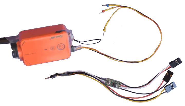 Top: RunCam 2 action cam with custom 3 wires cable powering the cam and triggering records. Bottom: Commercial cable with electronic converting RC PWM output to runCam2 control pulses pattern.
Cable exist to connect a RunCam2 action cam to an RC receiver for remotely start and stop a record from the receiver PWM output (20ms period, 1ms to 2ms duty cycle). The cable has logic to decode the RC PWM signal and generate the signal pulse scheme to start and stop the RunCam2 record.
Controlling the camera can be done with a microcontroller by generating the required pulse scheme described below.
The micro USB cable pinout is
- Pin 1 (VCC): +5V (higher voltage possible for the RunCam2 connector)
- Pin 3 (D+): TTL signal (5V)
- Pin 5 (GND): GND
When the Camera USB port is set for “Remote Control” and not for “mass storage” with the configuration application, it is possible to switch back and forth the camera from video mode to photo mode, and to start/stop recording, or take a picture.
The pulse scheme is the following:
- One pulse switch the camera from video recording mode to Photo mode.
- Two pulses separated with 85ms start or stop a video record (or take a picture in photo mode).
Pulse level is 5V but it works with 3.3V. Line is low state when idle. Pulses are 85ms in high state duration separated by 85ms on multiple pulse.
Tested with a runCam2 powered from a 3S LiPo battery (10 to 14V), no battery in the camera and pulse generated with a 3.3V dsPIC pin configured as digital output.
The figure below is the Simulink diagram with the logic used to generate the appropriate pulse on a dsPIC. Code is generated through the Simulink Coder and the MPLAB block from Microchip.
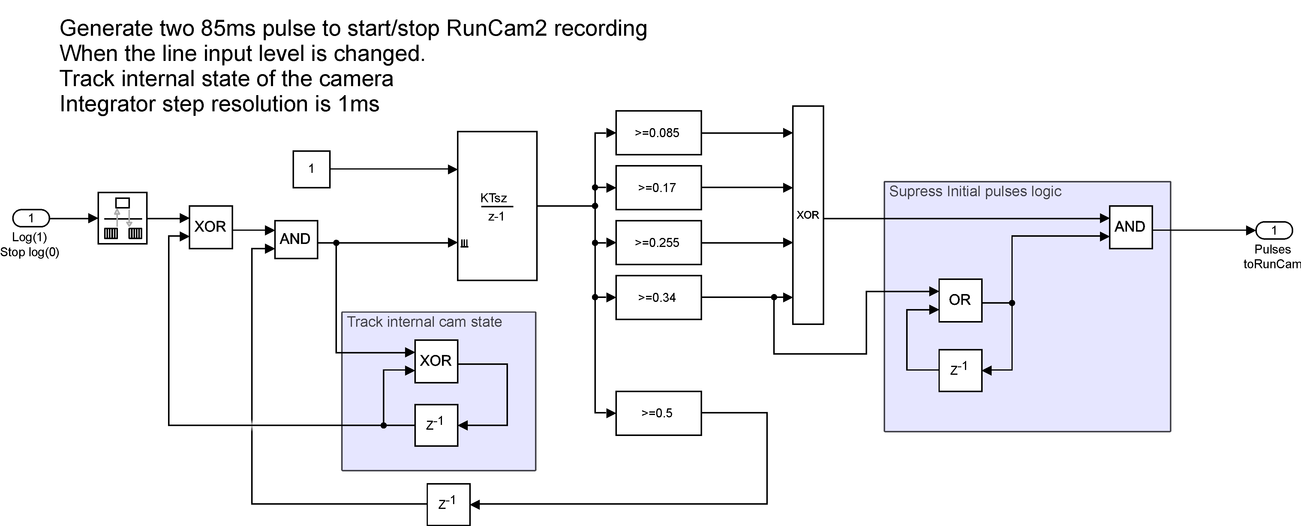
Simulink logic to control a runCam2 action Cam. The subsystem time step resolution is 1ms. The integrator is reset on each state change of the subsystem input, which trig the generation of two 85ms pulse pattern. Integrator reset is locked while pulses are being generated. Logic at the output of the integrator generate the pulses. The generated code was tested on a dsPIC target
Lubin Kerhuel
Engineer, PhD
Interested in signal processing and control theory. 10 years experience with rapid control prototyping.