Fixed-wing autopilot based on Simulink model
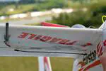
 Firstar 1600 plane
A 16-bits autopilot designed with Simulink and rapid control prototyping tools
Motivation
Building a platform for testing various autopilot control loop has become simple thanks to the many low cost elements available. To cite few of them:
- 10 DoF IMU: (~$5\ $$),
- GPS board: (~$10\ $$),
- Pitot tube (custom): (~$20\ $$),
- Microcontroller board: depend on the board; rely on $\approx 5\ $$ mcu,
- Plane platform: from $60$ to $120\ $$ including servos and motors.
- You also need few RC hardware:
- receiver
- remote control
- battery pack
- few optional hardware for data logging, telemetry, camera…
Difference with existing autopilot
Many off the shelf autopilot exists and works great. To mention few of them:
- Ardupilot
- PX4
- iNav
- LibrePilot
- Paparazzi.
- Others are listed on the DroneTrest review).
Usually, their internal parameters can be tuned. But, inserting your customized control-loop in such autopilot requires understanding the code structure underneath. Even well documented, it represents hundreds of C functions to navigate into, before starting any changes. Your custom control loop might not fit within the existing structure. You might want to implement a more advanced controller than existing PIDs, use a different sample rate etc…
Starting a new project is sometime faster than re-use a pre-existing advanced one. The presented autopilot uses a Model Based Design (MBD) approach: The autopilot code is generated from a unique Simulink model. Everything is within the diagram, from low level sensors handling up to the controller design. This MBD aproach is also named Rapid Control Prototyping (RCP).
The autopilot control-loop uses standard math blocks. Low level systems is taken care with the Microchip blockset driving the microcontroller peripherals. The UxV blockset provide easily access to GPS, Remote Control S.BUS, F.Port and Smart Port protocol, MAVLink messaging including Way Point and Parameters protocols. Such Simulink model allows to “get-in” the project graphically. It allows simulating parts of the system based on a simulated plane or based on values previously logged from a real flight which is helpful to design feed-forward sensor fusions algorithms.
Another key difference is the use of a 16-bit microcontroller while other autopilot uses 32-bit microcontroller. 16-bits dsPIC prove to provide all required resources thanks to the efficient architecture underneath which handle the many peripheral used in an efficient way (UART, I2C, Output Capture, Input Compare…).
Note however a similar model based design using dsPIC microcontroller beeing developed at UCSC by Pr G.H.Elkaim in a project named SLUG. Their design is independent from the one presented here. The original project handled by M.I Lizarraga [SLUG] (https://slugsuav.soe.ucsc.edu/) is available online. The update SLUG II projects rely on the same tool used here to target the dsPIC: the blockset for Microchip microcontrollers (free).
Hardware list
Various combination of material was tested. Below is a selected list of hardware which prove to be efficient.
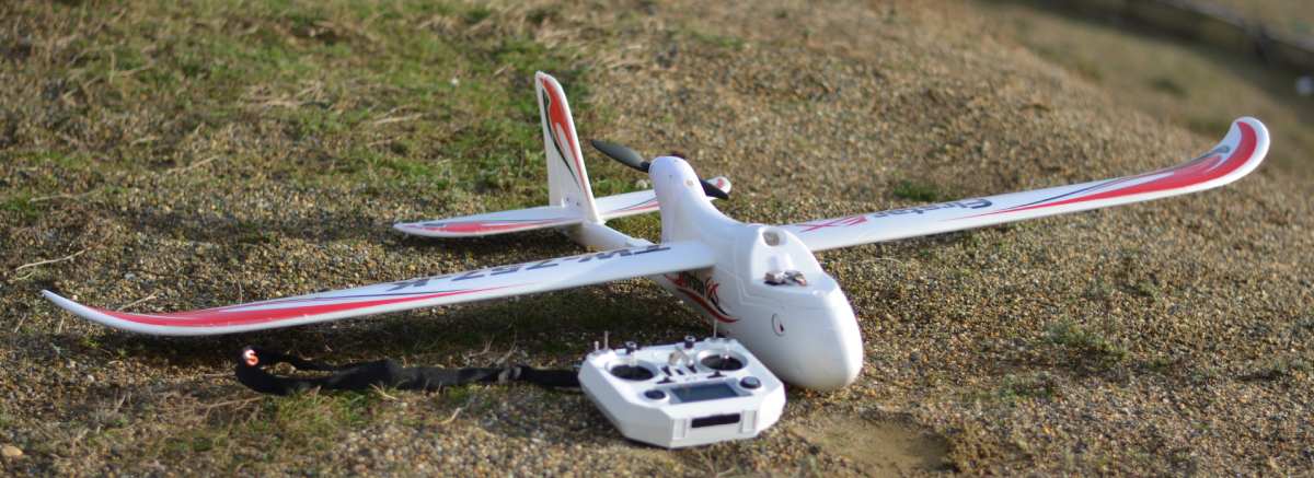
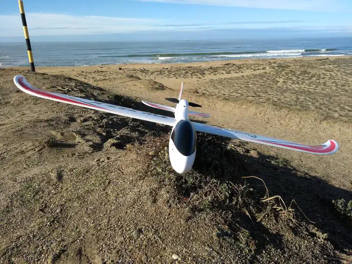
- RC platform: Volantex Firstar 1600 with stock motors and servos (Alternative platform are Bixler 2 and Ranger 1600)
- Remote Control: FrSky QX7
- Receiver: FrSky XSR-M / XSR used with either the S.Bus (receiver channel output) and Smart Port (Telemetry) protocol or with the F.Port protocol which combine both both S.bus with Smart Port saving one UART peripheral of the microcontroller. Each protocol uses only one wire thus half duplex UART. dsPIC UART peripheral enable configuring Tx and Rx on one line.
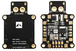
- Microcontroller: dsPIC 33EP on a AUAV V3 board. External motion sensor is used instead of built-in AUAV3 sensors. Tiny sensor board with recent chip are easier to firmly attach near the CG reducing vibrations. A custom board based on a dsPIC might replace the AUAV3 board which is difficult to find now. The UDB5 mini is similar and can still be found.
- IMU sensor: Gy-91 (10 DoF with 3 accelerometers, 3 rate gyro, 3 magnetometers and one barometer). Firmly attached near the CG of the plane. I2C bus is used between sensors and MCU.
- Pitot tube:
- An inner tube and an outer tube on which four holes are done laterally.
- Signal conditioning: the pitot tube pressure sensor (MP3V 5004 DP) is done with a MCHP ADC converter which integrate an analog amplifier. Converted pressure is sent to the microcontroller through the I2C bus. See build and test page.
- GPS: based on a $\mu$blox M8N chip providing up to 10Hz refresh rate and provided good results compared to competitors chips.
- Data logger: OpenLager board to log on SD card. It allows logging continuous UART output flow with at a baud up to 2 470 000 (much higher than a 115 200 baud rate that OpenLog data logger cannot sustain.).
- Radio link: 3DR Sik based Radio module for MAVLink telemetry (plane attitude, position, Way Point and Parameters tuning) with qgroundcontrol base station running on most platforms (PC, android, windows, Linux).
- Action cam: RunCam2 to film the plane and its surface control from the top; getting a visual behavior of the autopilot in the action.
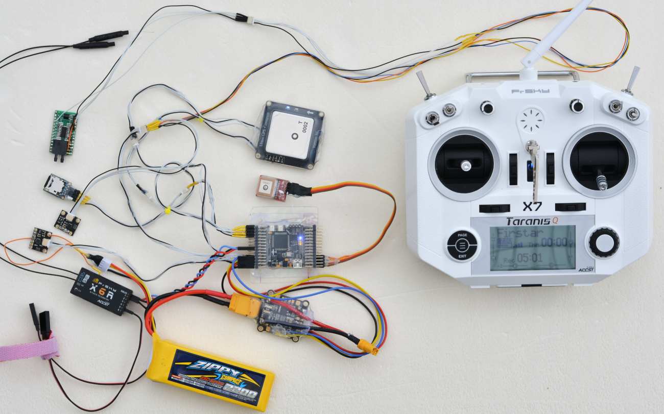
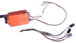
Embedded electronics. One early configuration for testing various sensors. Elements used: X8R receiver, PDB-XPM power board, OpenLager SD data logger, AUAV3 16-bit dsPIC microcontroller with sensors (MPU6050), IMU board 1, IMU board 2, Pressure sensor MP3V5004DP for pitot tube, GPS1, GPS2, 3S 2200maH LiPo battery, Qx7 transmitter.
Results
Sliding mode-based controller tested in both pitch and roll axis with two mode:
- Control plane angular rate control (angular speed set-point given through the remote control)
- Control plane angle attitude (angle set point provided through the remote control)
Average CPU load was 7 to 8% on a dsPIC 33EP running at 70 MIPS. It includes the IMU estimation algorithm, autopilot control loop and all low tasks (handle various protocols (I2C, NMEA for GPS, F.Port, MAVLink and log sensors data at 1Khz through an UART configured at 24700000)
Tested with strong wind. Showing good robustness despite the low number of parameters tuned so far (video link on top).
Pitot tube airspeed estimation validated using GPS speed measurement as reference (here).
Validated the wind speed and direction estimation based on a difference between the GPS and pitot tube speed measurement considering the plane orientation.
Validated automatic calibration of the magnetometer’s axis offset and gain. Once in the air, the magnetic perturbation near the floor are negligible. An algorithm automatically determines if the calibration can be refined using current data (using standard flight input data, no looping or specific roll required).
Next steps
Reduce chattering on ailerons when sliding mode control is enabled.
Test in flight MAVLink protocol parameters tuning.
Add automatic guidance of the plane, using MAVLink Way point sets.
Site content
Time constraints does not allow writing a complete description of the project as originally planned. Part of projects which I find interesting and inspiring will be posted.
Ideas to develop:
- IMU
- Pitot tube
- Wind estimation combining GPS ground-speed with Pitot tube airspeed
- UxV blocks including GPS, Remote Control and MAVLink blocks and functionalities
- Magnetometers auto calibration