block receiver & telemetry: S.BUS, Smart Port, F.Port
Three blocks add support for three protocol found in receivers. Traditional PWM output receiver can be handled directly through the Input Capture or Change Notification peripheral and do not required a specific block.
S.BUS, Smart Port and F.Port
S.BUS, Smart Port (also named S.Port) and F.Port are three protocol available in FrSky RC receiver and compatible. All three protocol rely on the UART peripheral with different settings. Their purpose is specific:
- S.BUS is a unidirectional protocol from the receiver to an external device to provide channels values and RSSI1 (i.e. radio link quality).
- Smart Port (S.Port) is a bidirectional protocol. The receiver ping for various connected sensors and retrieve measurements to send through telemetry to the remote control.
- F.Port is a bidirectional protocol where the receiver communicate channels values and RSSI, and get values from connected sensors to send through telemetry to the remote control.
The two bidirectional protocol Smart Port and F.Port use one single wire for Tx and Rx. Communication is done in Half duplex mode.
FrSky receiver have two variants: (model shipped with Smart port: x4r, rx4r, x6r, s6r, rx6r, x8r, s8r, xsr, xsr-m, r-xsr …)
- S.Bus & Smart Port (stock), available on two distinct three pins ports
- F.Port available on one replaced Smart Port three pin port
Stock receiver have two ports: S.BUS and Smart Port. This is changed for a unique F.Port by flashing an alternative firmware provided by FrSky. The alternative firmware remove the S.BUS port and convert the Smart Port to an F.Port.
UART settings and implementation
S.BUS, S.Port and F.Port have different UART setting defined in the table:
| Baudrate | Duplex | Logic | parity | stop-bit | flow-ctrl | |
|---|---|---|---|---|---|---|
| S.BUS | 100000 | Rx only | 3.3V inverted | even | 2 | no |
| Smart Port | 57600 | Half | 3.3V inverted | no | 1 | no |
| F.Port | 115200 | Half | 3.3V inverted | no | 1 | no |
Implementation on dsPIC with the MPLAB block for Simulink was successfully used with the implementation below set through the UART Configuration block:
| Implementation | Buffer size | Interrupt priority | |
|---|---|---|---|
| S.BUS Rx | Circular Buffer | 64 | 5 |
| S.BUS Tx | None | - | - |
| Smart Port Rx | Circular Buffer | 32 | 5 |
| Smart Port Tx | Circular Buffer | 32 | 6 |
| F.Port Rx | Circular Buffer | 32 | 5 |
| F.Port Tx | Circular Buffer | 64 | 5 |
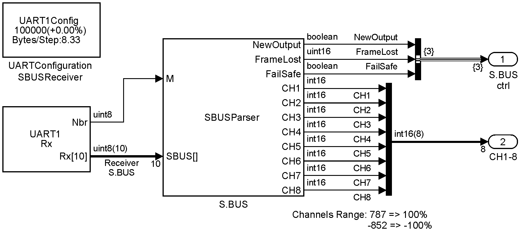
Connecting S.BUS, Smart Port and F.Port simulink blocks to UART Rx & Tx
S.Bus, F.Port and Smart Port xxx takes receiver output stream to extract control values sent by the remote. The input stream is a vector which length is defined by end user. All values of the vector do not have to be set. The block use the N input length scalar to know how many bytes from the input vector are received values and must be processed. The block input vector can received partial data packet. The whole receiver packet can be sliced over time and sent as values are received by the MCU ; these blocks reconstruct the packet before processing it.
S.BUS protocol
UART Configuration:
Only Rx channel is used with the following parameters:
- 100 000 bauds/s
- Rx inverted logic (Idle state is low level), 3.3V
- Even parity
- 2 stop bits
- No control flow
Rx is implemented with a Circular Buffer with 64 bytes buffer and interrupt priority 5.
UART Rx block is sampled at 1kHz (1ms). Vector output size set to “inherited via internal rule” is given a value of 10 (no more than 10 bytes can be received in 1 ms at 100000 bauds/s with two stop bits)
The S.BUS block GUI allows to set which block output shoudl be decoded and the scaling for each channels decoded.
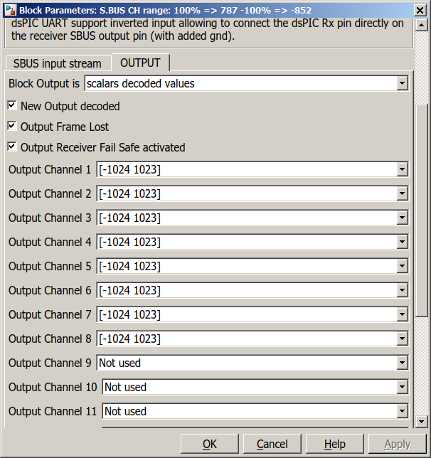
Simulink S.BUS block user interface
This simulink block decode S.BUS input stream. Scaling for output RC channels can be selected for each channels.
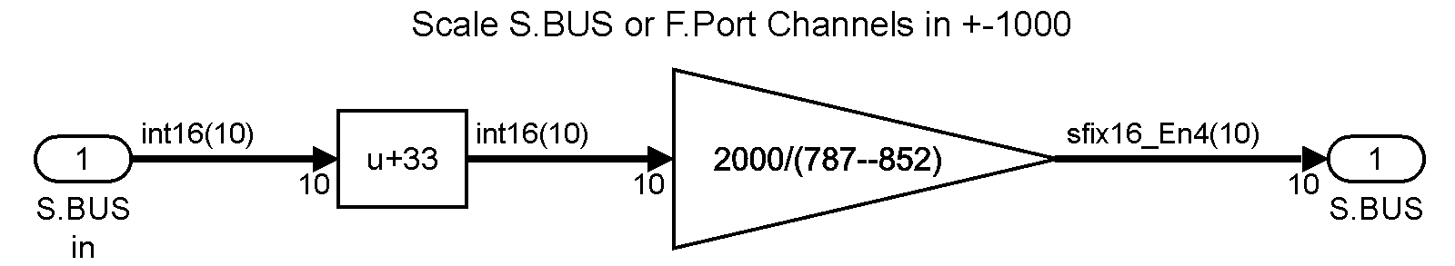
Scheme to center and scale S.BUS channels output within [-1000 1000]
raw values from S.BUS are not centered and scaled with power of 2.
Smart Port protocol
Smart Port (S.Port) use UART where Rx and Tx pins are set on the same pin with inverted logic (1 is high level). One single wire is used in half duplex communication mode.
UART configuration setting:
- 57600 bauds/s
- Half duplex
- Rx and Tx inverted logic (Idle state is low level), 3.3V
- No parity
- 1 stop bit
- No control flow
Implementation:
Rx is implemented with a Circular Buffer with 32 bytes buffer and interrupt priority 5.
Tx is implemented with a circular buffer with 32 bytes buffer and interrupt priority 6.
The Smart port block decode inputs from the receiver and from other sensors connected to the one wire bus.
If a sensor frame is received, it is decoded and values are available at the block output.
When a receiver request for one sensor Id is received and if this sensor Id is set in one of the sensor block of the model, then the Smart port block generates the sensor frame with the latest values set in the sensor block. The message is sent through an UART Tx block.
F.Port protocol
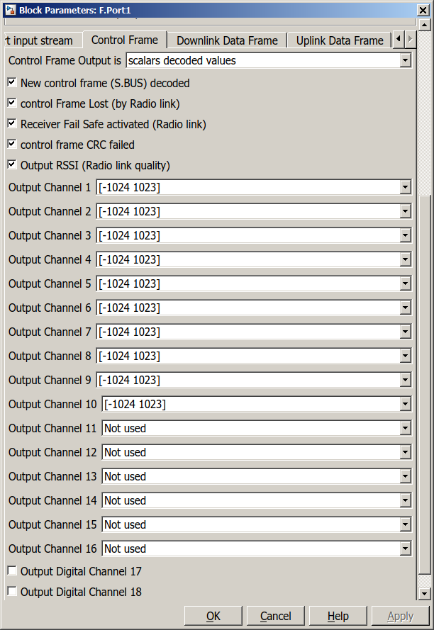
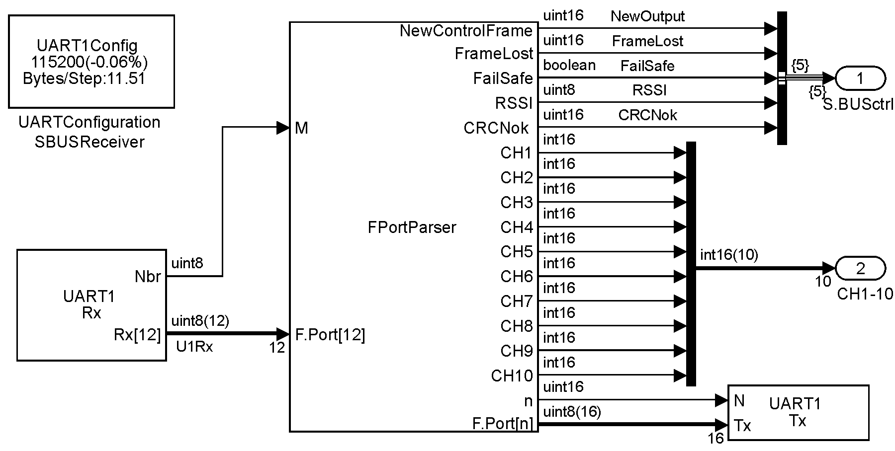
UART configuration: Rx and Tx channels are used. They are assigned to the same pin. UART is configured for to half duplex.
- 115200 bauds/s
- Half duplex
- Rx and Tx inverted logic (Idle state is low level), 3.3V
- No parity
- 1 stop bit
- No control flow
Rx is implemented with a Circular Buffer with 32 bytes buffer and interrupt priority 5.
Tx is implemented with a circular buffer with 64 bytes buffer and interrupt priority 5.
Ressources
FrSky protocol are not always documented. The following website helped understanding the various protocol:
- Smart Port on ROBOTmaker
- Smart Port on telemetry-convert project
- Smart Port TelemetryScript by Allesandro Apostoli
- S.BUS on Arduino lib project
- Smart Port on MavLink-FrSkySPort project
- betaflight source code
- ArduCopter project
- SBUS2 by Jerry Chapman
Received Signal Strength Indicator ↩︎